
[ Software Settings | Meters | Stop Watch | Logfile || Main Help Index ]
[ General | DAQ | Substrate | LEED System | License | NetCDF | Help | Ranges ]
In the Software Settings window, you can customize several global program settings such as colours, paths and specific parameters of your LEED system and data acquisition hardware. For all tabs there are the "Apply" and "Default" buttons for applying the settings in the currently opened tab or for loading the default settings.
The general software settings tabs contains some global settings of WinSPA that are not related to SPA-LEED at all. You can (should!) set the installation and data paths and your standard printer. A change of the colour scheme of the scan data displays is optional, but may be necessary depending on your colour scheme (Microsoft XP Luna, Microsoft Vista Aero).

| GUI Element | Meaning and Usage |
|---|---|
| Program Path | Path of the WinSPA installation; config.dat, netcdf.dll and SpaDAQ.dll are expected here. |
| Data Path | Default path for all file save/load operations and the logfiles. |
| Marker Colour | Colour of all markers, such as for the active scan line. |
| Background Colour | Colour of the background area of data displays. |
| Lines and Text Colour | Colour of lines and text in data displays. |
| Scan Data Colour | Colour of scan data in 1D displays. |
| XOR Colour | Colour for XOR plotting of graphic tools etc. |
| Colour Scheme Preview | Small preview of your choice of colours. The colour table is by default the grayscale. |
| Current Printer | The printer for all printouts. |
Note: The log file is written into the folder specified by the data path. Earlier releases of WinSPA (including V1.0) used the program path for the logfile.
In the DAQ tab in the Software Settings window you can define the basic settings of your SPA-LEED system. The values of deflection and emitter high voltage amplifier gains have to be correct for proper operation of WinSPA with your hardware.

| GUI Element | Meaning and Usage |
|---|---|
| Deflection Amplifier Gain | Voltage gain of your deflection amplifiers. |
| Emitter HV Amplifier Gain | Voltage gain of your emitter high voltage amplifier. |
| DAQ Hardware | Your currently used DAQ hardware. This is for your information only. |
| Bidirectional 2D Scans | In a Bidirectional 2D Scan, the scans lines are alternately scanned
from the left to the right and from the right to the left.
This avoids large deflection voltage steps during a scan. |
| Direct Retrace Scans | In a Direct Retrace Scan, after finishing a scan line
the deflection voltages of the first point of the scan line are set.
This allows the deflection voltages to settle while the display is updated etc. |
| Messages (of Scan Engine) | Click here to view the scan engine messages. |
| Beam Park Position | Deflection voltage outputs during idle times. |
Note: The "bidirectional scan" and "direct retrace scans" settings have to be used carefully: They are meant for optimising the timing of scans and high voltage amplifiers. Consider also the timing factors in the "LEED system" tab.
Hint: Take a 2D scan with a small gate time (1 ms or less) with the "bidirectional scan" setting active, and observe the inter-digital-like shifts of the scan lines. If these shifts are small, you may use the "birectional scan" setting and not delay timing (see next tab) for fastest possible scans. If the shifts are large, you should introduce delays to allows for high voltage settling.
Note: The beam park position is used to protect your channeltron during idle times, since the latter's lifetime at the
106 counts per second from a specular spot is limited to only a few hours.
Check always that your park position setting does not accidentally coincide with a diffraction spot position.
In the Substrate Settings tab you can change the parameters describing the surface of your current sample. This is necessary for the internal calculation of reciprocal space units.
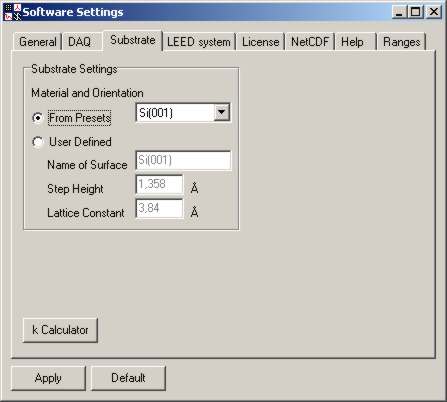
| GUI Element | Meaning and Usage |
|---|---|
| From Presets / User Defined (substrate) | Choose either from preset list or directly enter substrate parameters. |
| Preset substrates dropdown list | List of predefined substrates you can choose from. |
| Name of Surface | Name of substrate, for identification in list only. |
| Step Height | Step height of substrate, needed for scattering phase calculation. |
| Lattice Constant | Lattice constant of substrate, needed for %BZ calculation. |
| k Calculator | A calculation tool for various units conversions. |
Note: If you frequently use other samples than the predefined ones, you can add them to the samples list in WinSPA's config file.
In the LEED system tab you can set several parameters of your SPA-LEED system,
including geometry and beam deflection values.
All those values have - assumed that the measurement geometry does not change
anymore - only to be set once, independent of your sample.

| GUI Element | Meaning and Usage |
|---|---|
| Internal / External geometry | Select whether you are using the internal or external geometry as described in the "hardware" section. |
| Internal angle between ki and kf | Angle between incoming and reflection electron beam in internal geometry. Can be calculated from the distances sample-detector and gun-detector. |
| External angle between ki and kf | Angle between incoming and reflection electron beam in external geometry. Can be calculated from the three distances detector-sample, sample-external gun, external gun-detector. |
| k Sensitivity | Deflection of beam in diffraction mode, normalized to electron energy. |
| R Sensitivity | Deflection of beam in real-space mode, normalized to electron energy. |
| Use delay after E changes | Planned to be implemented in V 1.03. |
| Use delay after Ux and Uy changes | Planned to be implemented in V 1.03. |
| Use pulse heating time stretch | Planned to be implemented in V 1.03. |
| Test xy wiring | Click here to test the correct x-/y-wiring. |
| XY Offset V(oltage)s | Click here if you want to set deflection voltage offsets manually. |
| Manual E (setting) | Click here if you want to set the electron energy manually. |
Note: If you are using an Omicron third-generation SPA-LEED with a sample distance of 15 mm, then the preset settings are correct. In other cases, please take the necessary time for measuring and calculating (angles) as well as calibrating (sensitivities).
For adjustment purposes and for a correct RSM scan alignment you can set offsets on the deflection voltage in the x- and y-directions. During "normal" operation the offsets should be set to zero, since a good mechanical alignment of your sample is independent of the electron energy and therefore better than electrical shifts.
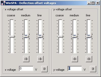
| GUI Element | Meaning and Usage |
|---|---|
| x voltage offset coarse/medium/fine | Three sliders with different ranges for changing the X offset voltage. |
| >||< ("Center") x voltage Offsets (medium/fine) | If the medium or fine slider of the X offset voltage is at one end of the range, you can transfer most of its value to the next coarser slider. |
| x voltage | Display of the X offset voltage. |
| 0! (Set x voltage to zero) | Click here to center all sliders and thereby reset the X offset voltage to zero. |
| y voltage offset coarse/medium/fine | Three sliders with different ranges for changing the Y offset voltage. |
| >||< ("Center") y voltage offsets (medium/fine) | If the medium or fine slider of the Y offset voltage is at one end of the range, you can transfer most of its value to the next coarser slider. |
| y voltage | Display of the Y offset voltage. |
| 0! (Set y voltage to zero) | Click here to center all sliders and thereby reset the Y offset voltage to zero. |
In some situations, you may want to set the electron energy manually and directly , for example to find an out-of-phase condition, mainly when you are looking at the phosphor screen of your SPA-LEED. In case the SPA-LEED supply is too far away to reach the energy control while looking at the phosphor screen, "manual energy" allows you to use mouse and keyboard (extension cables may be useful) to change the electron energy quickly and observe the effect immediately.
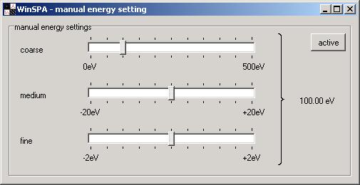
| GUI Element | Meaning and Usage |
|---|---|
| manual energy coarse/medium/fine setting | Three sliders with different ranges for changing the electron energy manually. |
| active | Click here to activate the manual energy setting. Consider the "note" below. |
Note: WinSPA actually crashes if the manual energy setting is used in parallel to the execution of any scan. This is known and not really a bug, but rather caused by the way the energy setting and scan execution are handled internally. This may be changed sometime in the future, but in fact there is really no good reason for tinkering with the electron energy during scanning!
In this text field detailed information is shown about the owner of this copy of WinSPA. This license information will only gnaw at the guilty conscience of all illegal users of WinSPA but give honest customers a good feeling of having done the right thing.

Note: WinSPA does not use any copy protection mechanism at all, in order to allow
you to view and analyze your scan data on any other computer (laptop etc.).
You don't have to deal with registry variables, hidden files, dongles
or anything annoying like this.
Please buy a license, however, for each SPA-LEED system
you are operating with WinSPA. The development and maintenance of this
software was and is time consuming, and the price is comparably low
compared to all associated UHV hardware parts.
WinSPA uses the free data format NetCDF (network Common Data Format). NetCDF is a machine-independent format for representing scientific data. This format is widely used in the scientific community. NetCDF files can be handled by numerous software products such has IDL (native) and Matlab (requires a toolbox). C, Fortran, Java, etc. libraries are also available to read/write netcdf data files.
In particular, NetCDF data is
All information on how to deal with netcdf format can be retrieved at Unidata. Free NetCDF browsers for viewing data are also available (NCbrowse and Panoply).
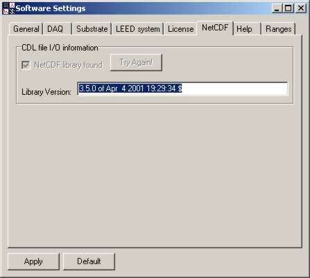
| GUI Element | Meaning and Usage |
|---|---|
| NetCDF library found | This checkbox is activated if WinSPA was successful in loading the netcdf.dll library. |
| Try again! | Click here to let WinSPA search again for the NetCDF library.
You could place the netcdf.dll file in the WiNSPA directory. |
| Library Version | Here the version of your netcdf.dll library is displayed.
WinSPA was developed and tested with V 3.5.0 (4th April 2001). |
In the NetCDF tab you can see whether the dynamic link library (DLL) for NetCDF file access has been found or not. You should check this after the installation of WinSPA. If the DLL has not been located by WinSPA, re-check the presence of the netcdf.dll and click on the try again button.
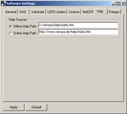
In the help path settings tab you can change the paths where WinSPA expects the help files.
| GUI Element | Meaning and Usage |
|---|---|
| Offline / Online Help Path | Choose whether you want to use the offline (as delivered) or online help of WinSPA. The first is surely available in the WinSPA program path, but the second is probably more up to date. |
| Offline Help Path | The path of the WinSPA offline help files on you computer system. |
| Online Help Path | The path of the WinSPA online help files on the world wide web. |
The values of many graphical user interface input elements of WinSPA are checked to be within a defined range of allowed values. Even though this patronizes the user, severe problems can be avoided this way, such as
There may be, however, situations where the user does not want the software to try to be more intelligent than the user. For example, you may want to make a 2D scan with 10,000 by 100 pixels, knowing that this costs less memory than the default 4000 by 4000 pixels. Or you might want to view a 100 by 100 pixels 2D scan in 20 times magnification, knowing that this would not be a good idea for a 4000 by 4000 pixels 2D scan since the internal graphics memory might not be sufficient.
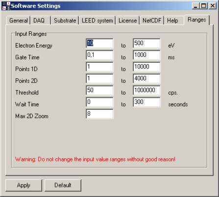
In those cases only you might change the range settings of WinSPA. Please think twice why the preset ranges are not sufficient for your application and whether any problems could be caused by exceeding the predefined ranges. Also, please set the default values immediately after you have finished the scans for which you needed the extended settings.
Note: Since the standard settings are considered to be correct for all "normal" applications of SPA-LEED, your changed settings are not saved in the config.dat file - they are only valid until closing WinSPA.
| GUI Element | Meaning and Usage |
|---|---|
| Electron Energy Min. / Max. | Minimum/maximum allowed values for the electron energy. |
| Gate Time Min. / Max. | Minimum/maximum allowed values for the counter gate time. |
| Points 1D Min. / Max. | Minimum/maximum number of scan points in 1D scans. |
| Points 2D Min. / Max. | Minimum/maximum number of scan points in each direction in 2D scans. |
| Threshold Min. / Max. | Minimum/maximum value of threshold intensity in spot tracker for point scans. |
| Wait Time Min. / Max. | Minimum/maximum value of wait time between repetetive scans. |
| Max. 2D Zoom | Maximum image zoom for all 2D scans (2D, SEM, RSM). |
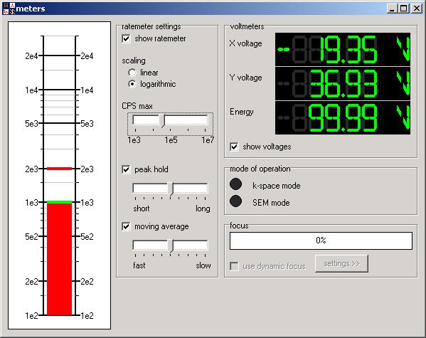
In the "meters" window you can find some display elements for
checking and controlling the I/O data of WinSPA, such as
count rate, deflection voltages, electron energy and more.
All those values are displayed via a callback function from the SpaDAQ.dll.
That means that they come from a very deep abstraction layer of the software.
You can therefore be pretty sure that these values are correct
(depending on the voltage gain of your deflection and emitter
high voltage amplifier).
The drawback of this callback approach is a greatly reduced system performance
(bidirectional communication with data acquisition library)
and lots of problems with a thread-safe and lock-proof access of the
Delphi VCL (visual control library).
Therefore, if you need those values for debugging or adjustment purposes,
use the meters window. But don't display those values all the time
just because it is possible.
Note: The values are updated when and only when SpaDAQ.dll updates the output values. In order to minimize hardware access, the values are only written to the hardware if and only if a value has changed. You might therefore see E=000.00eV quite some time after switching on the "show voltages", even though the electron energy is not 0 eV. This value is only updated after current electron energy is changed the first time after switching on the display (the same holds for the deflection voltages).
| GUI Element | Meaning and Usage |
|---|---|
| Rate Meter Display | In this display field a bargraph display of the current count rate is visualized, along with lines for peak hold and moving average (if active). |
| Show Ratemeter | Switch the ratemeter on or off. |
| Linear / Logarithmic Scaling | Linear or logarithmic scaling of the ratemeter. |
| CPS Max. | Upper limit of the ratemeter display range. |
| Peak hold | Switch display of peak hold on or off. Peak hold value is displayed as thick line in "data color". |
| Peak hold time range | Duration for peak hold memory. |
| Moving Average | Switch display of moving average on or off. Moving average value is displayed as thick line in "marker color". |
| Moving Average speed | Time constant for moving average. |
| X Voltage | X deflection voltage Ux. |
| Y Voltage | Y deflection voltage Uy |
| Energy | Electron energy UE. |
| Show Voltage | Switch display of Ux, Uy and UE on or off. |
| Mode of Operation (k-Space / SEM) | Status of logical output for controlling an optional relay switch for deflection voltages. |
| Focus | ...not yet implemented, coming soon. |
| Use dynamic focus | ...not yet implemented, coming soon. |
| Focus settings | ...not yet implemented, coming soon. |
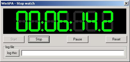
The stop watch is a small but very helpful tool for efficient measurements. It basically defines a local time in in-situ experiments for the start of measurement, deposition etc..
Not being meant as a replacement for a well-documented lab book, of course, the "log this:" allows you to store short text information along with a precise time stamp into the text log file of WinSPA. The text information may usually be something like "evaporator shutter opened", "sample to 500K" or "refocused".
| GUI Element | Meaning and Usage |
|---|---|
| Time display | Display of the stopwatch timer's local time. |
| Start | Start the stopwatch timer. |
| Stop | Stop the stopwatch timer. |
| Pause | Pause the stopwatch timer. This may be used if you interrupted a deposition in between, but you should normally not need this function. |
| Reset | Reset the stopwatch timer. |
| log this: | Click here to write a comment text line into the log file, along with a precise time information.
Typical examples are: "Start of deposition", "Focus changed", "Emission reduced", "sample flashed" and so forth. |
| Log Text | Text line to be written into log file. |
WinSPA saves all scan events (start/stop of scans), stopwatch actions and text comments ("log this:") into the log file. This file can therefore be a valuable help for your data analysis, since even complex measurements can be sorted and analyzed afterwards.

The start times of the scans are also written into each scan file, as well as the local stopwatch time. This information is therefore redundantly saved. Your comments and all start/stop information of scans you do not save to disc are only written into the logfile.