[ SEM | Opti || main help index ]
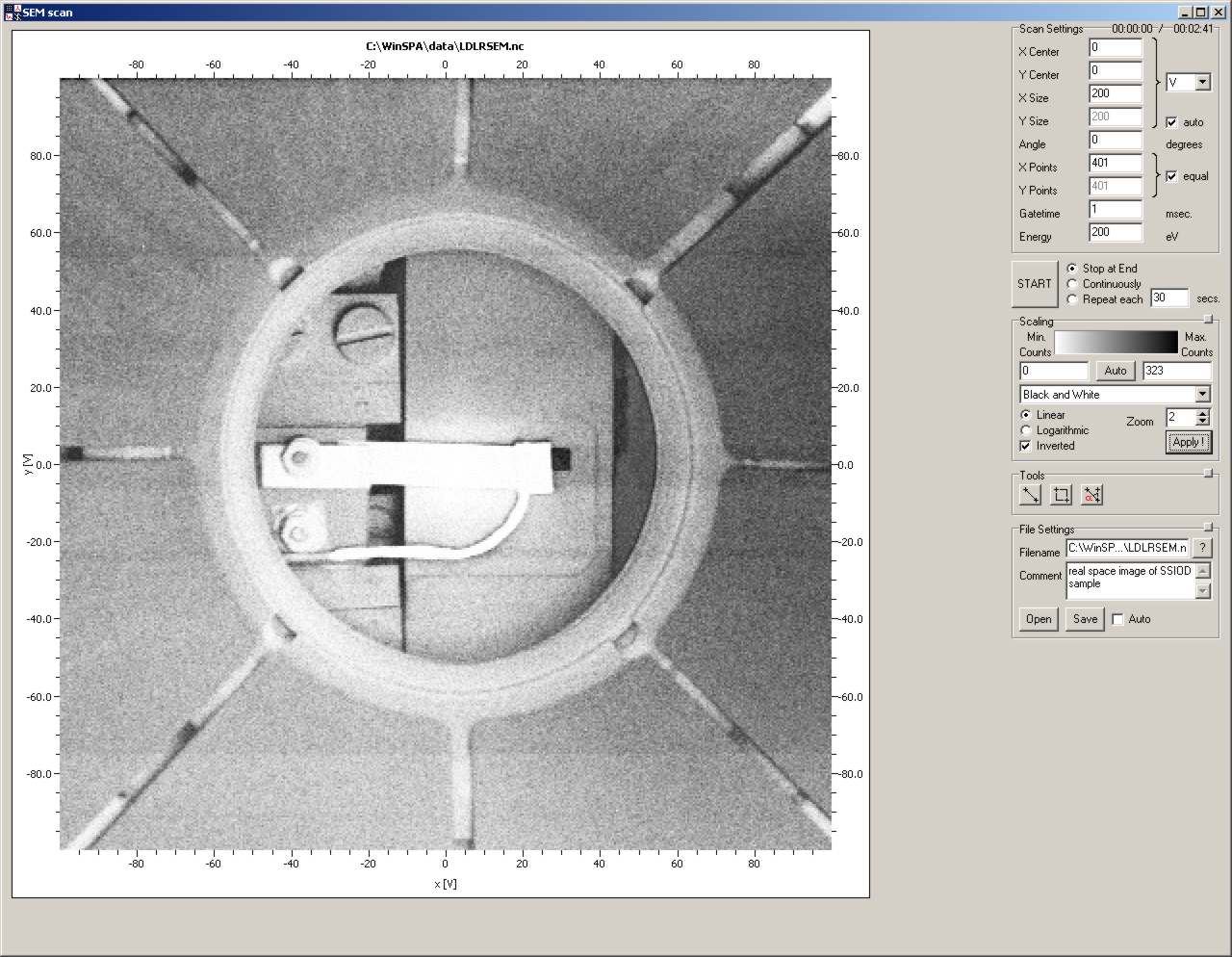
WinSPA features another two scan modes, the scanning electron microscopy (SEM) scan - sometimes called LDLR-SEM (long distance, low resolution - SEM) - and the real time single spot display, the "opti" scan. These two scan modes are not really suited for the acquisition of data which can be analyzed and published, but rather for maintenance and adjustment measurements.
[ scan settings | scan action | tools | scaling | file | context menu ]
In the usual SPA-LEED scanning mode, front and rear octopole deflectors are oppositely charged in order to deflect the primary and secondary electron beams in an S-shaped trajectory. If the two octopole deflectors are connected identically then the primary electron beam is deflected just as in a cathode ray tube (CRT) display. Electrons are scattered wherever the electron beam hits the internal parts of the SPA-LEED, the sample holder and the sample itself. If the setting of the channeltron suppressor allows the detection of inelastically scattered electrons then images of the real space can be acquired in a very similar manner to a scanning electron microscope (SEM). The contrast mechanisms are geometrical contrast (inclination of surfaces), chemical contrast (work function) and field contrast.
Note: The count rate in real space mode is much higher than in diffraction mode, since inelastically scattered electrons are detected. Keep an eye on the count rate of your channeltron and reduce the count rate with the repeller if necessary.
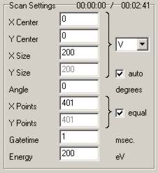
In the Scan Settings group box you can choose how the real space scan should be executed. You can change all the parameters that determine the size, resolution and appearance of the real space scan.
| GUI element | Meaning and Usage |
|---|---|
| X Centre, Y centre | Coordinates of the centre of the scan. |
| X Size, Y Size | Extension of the scan in both directions. |
| Auto Y Size | Turns automatic calculation of the y size on and off.
The y size is calculated to be dy = (Ny/Nx)*dx in order to yield a correct aspect ratio. Turn this off only if you want to scan in one direction with higher resolution than in the other. |
| Scan Units | The units of x,y centre and size parameters (Volts or mm).
The conversion factor depends on your LEED system and the distance between SPA-LEED and sample and it can be changed in the "Software Settings" window (>LEED system>R sensitivity). |
| Angle | Angle of anti-clockwise scan rotation around center of scan. |
| X Points, Y Points | Number of scan pixels in each direction. |
| X Points equal Y Points | Turns the locking of the number of Y Points on and off.
Usually (i.e., in 98 percent), SEM scans are quadratic with Nx=Ny. |
| Gatetime | The gate time used for each pixel.
Higher gate times reduce the relative noise with O(1/Sqrt(t)) but increase the scan times with O(t). Typical values are between 1 ms and 15 ms. |
| Energy | Electron energy. The energy in real-space mode can be chosen much higher than in diffraction mode. Typical values are around 220 eV. If you use the SEM scan for debugging, you might want to use the same electron energy as in diffraction mode in order to observe charging effects etc. correctly. |
These tools are not nearly as important as their counterparts for the 2D scan but they can be useful for adjustment problems like "how far do I have to move the sample left to hit it in the centre?" or "how much do I have to turn the sample clockwise to make their sides parallel to the x and y axes of my SPA-LEED?".

| GUI element | Meaning and Usage |
|---|---|
| Ruler Tool | This allows you to measure distances between any two points within the SEM scan. |
| Retangle Tool | The rectangle tool can be used to define a new scan area. |
| Angle Tool | The angle tool helps you to determine angles within the SEM scan. |
[ data displays | scan settings | spot analysis | display options ]
The spot profile optimization window allows you to quickly execute small scans around a single LEED diffraction spot and to determine its width and position in real time. Combining this with a fast spot tracking, allows you to find the optimum focus for a LEED spot.
The form is divided in four sections: The data displays on the left, the Scan Settings group box right of the middle, the Spot Analysis group box on the top right, and the Display Options group box on the bottom right.
On the left side of the Opti form there are four graphs displaying properties of the spot being currently scanned. You can change the size of the scans with the "Scan Size" slider in the "Scan Settings" group box.
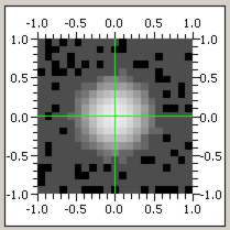
The display on the upper left shows a 2D scan of the LEED spot currently being scanned. Since the scan time for a 2D scan scales with the pixel resolution in one direction to the power of two, this display must be explicitly activated. See "Display Options" for more information.
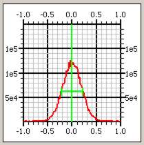
The two 1D scan displays show 1D scans in x- (upper right) and y-direction (lower left) scans through the center of the quadratic region of interest.
The position control display on the lower right shows the differences between the last N (N~20) spot positions and the current spot position. If the Auto Align is not active (default, see "scan settings"), the position control gives an impression of the spot motion. If the Auto Align is active, the position control gives an information about the stability of the combined aligning and the spot position.
Note: In 90 percent of the time you are using the Opti window you should see only a tiny point in the center of the position control. Anything else means a significant spot motion or an instability of the Auto Align.
In the scan settings group box you can change most of the parameters for the opti scans such as scan size, resolution and gate time. The preset values should work most of the time, use extreme settings only after consideration.
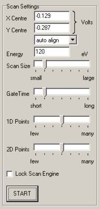
| GUI element | Meaning and Usage |
|---|---|
| X Centre, Y Centre | x and y coordinates of the centre of the scans. |
| Fixed / Autoalign Position | If you choose autoalign then the scan center will be adjusted to the last spot centre and the new coordinates will be displayed as the x center and y center values. This, of course, does only make sense if the spot analysis is active. As long as "autoalign" is active and the spot motion between two scans is smaller than the scan size, you can concentrate on optimizing the spot shape without having to care about its position. |
| Energy | The electron energy.
If you are aligning the internal electron gun, you should look at the (00) spot and then iterate the following: Focus the spot at a low energy (~60 eV) with the offset potentiometers on your LEED supply and then focus the spot with the gain potentiometers at a high energy (~250 eV). |
| Scan Size | The scan size determines the size of all three scans and the position control. For ease and speed of use there are a couple of scan sizes predefined. |
| Gate time | The gate time is the gate time for all three scans. |
| 1D Points | Number of points for 1D scans. |
| 2D Points | Number of points in each direction for the 2D scan.
Keep an eye on the frame rate information in the display settings group box! |
| Lock Scan Engine | Since it does not make too much sense to use the opti window while other scans are running, you can define the opti scan as the exclusive scan thread. This saves a bit of scan time because the scan time dispatcher is not being used. |
In the spot analysis group box there are several edits to display quantitative information about the currently scanned LEED spot. The width (=FWHM, full width at half maximum value) is determined from the two 1D scans by finding the maximum intensity and then going left and right until half of that intensity is found. This simple analysis is very quick and very stable, but it might yield not very precise result if either the scan size is smaller than about twice the spot width or the background intensity is comparable to the spot intensity. The total spot width is calculated by the square root of the sum of the square of the x and y spot width. This value is not a good estimate for the real total spot width if the diffraction spot is diagonally elongated.

| GUI element | Meaning and Usage |
|---|---|
| Live Profile Analysis | Turns the analysis of the two 1D scans on or off.
You can set this "active" most of the time; required CPU time is quite small. |
| X,Y Width | Width of the spot in x- and y-direction as determined from the 1D scans. |
| Total Width | Total width of the spot as described above. Use this as a measure for the over-all-focus-quality. |
| X,Y Position | X and Y position of the spot.
These are calculated via a centre of mass algorithm and do not depend on the spot shape. This method is very stable but inaccurate if the spot is partly outside the scan area or several spots are inside the scan area. |
| Peak Intensity | The maximum intensity of the diffraction spot. |
In the display options group you can change some settings that determine the display of the small opti scans, such as scaling and the display of spot information.
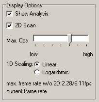
| GUI element | meaning and usage |
|---|---|
| Show Analysis | Turns the display of spot center and width on or off. You can leave this on most of the time. Turn it off if the spot is outside the scan area to avoid the bothersome display of senseless data. |
| 2D Scan | Turns the 2D scan on and off.
Note: This is not really a display setting: The 2D scan is not being executed, if the "2D scan" checkbox is not activated. Maybe it is a bit confusing that this is placed in the "display" section, but thus you HAVE to look at the expected frame rates before freezing you computer system :-). |
| Max. Cps | The upper limit of the y axes of the 1D scans, corresponding to a white pixel in the 2D scan. |
| 1D Scaling | Choose whether you prefer linear or logarithmic scaling for the 1D scans. The 2D display is always logarithmic. |
| Frame rate information | On the lower right you see some information about the possible
frame rates (=repetition times of scans) with and without a 2D scan.
Take a look here before switching on the 2D scan. Depending on gate time and resolution, a 2D scan can easily take several seconds! The current frame rate is usually a bit smaller than the calculated one, since operating system, data display and scan engine internal administration require also some CPU time. |